
This is a sub-section of my posts describing the Sustainable Energy Design 3 course group project to Design and Build a Micro Wind Turbine – for more information see here
The Design
For maximum efficiency we are using a full wave rectifier. The two most common options for this are diode bridge rectifiers or transformer bridge rectifiers – the inclusion of transformers means less diodes are needed, but is considerably more financial cost and time and generally used when a transformer is to be used anyway. Therefore we are using a 3 phase diode bridge rectifier instead.
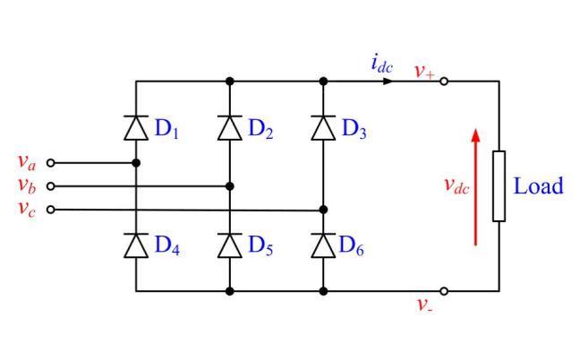
This means that we are creating a voltage drop across each diode which would normally be around 0.7V for ‘normal’ NPN transistor based diodes, but this as 1.4V is a significant loss proportional to 12V, and so to reduce this we are using Schottky diodes. These only have voltage drops of around 0.15V to 0.45V. They do add additionally cost of a few pounds which would be significant in most widespread applications where large numbers of diodes are in use but is minimal in our rectifier application.
We used the generator calculations to estimate the voltages and currents produced to give IACmax of about 5A and about 15V.
We specified an ideal theoretical output of peak 15V from the generator design. The average DC output from the rectifier should in theory be approximately this, minus the voltage drop across the 2 Schottky diodes encountered through the rectifier, multiplied by 2/pi, displayed in Equation 1.

As this voltage is too low to charge the battery, we will need to use a boost converter to amplify the voltage later.
The output from the rectifier will be pulsed, even if not AC, and the pulses will be especially pronounced if any of the coils are mismatching or damaged as they are in the stator we have manufactured. This can damage the components in the charging circuit if we are not careful, and additionally creates a lot of noise for the current and voltage readings that the microcontroller will have to interpret, a task especially difficult as will not be taking continuous readings but successive discrete ones which may be timed at different points in the pulses. Therefore we should add an inductor and capacitor in to smooth the output – these ideally need to be quite large to accommodate for our high power output but large inductors and capacitors are very expensive so we will have to go for sub-optimal values for our prototype.
Testing
Single Phase (Individual Diode) Testing
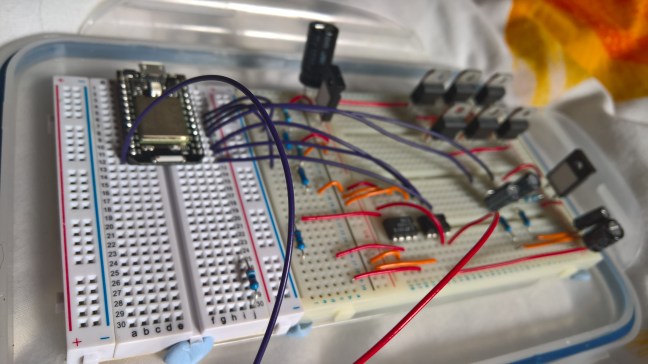
Initially each phase of the rectifier was tested individually, to identify if there were any unique faults, as the Schottky diodes may needed to be individually replaced, using a low power supply to input an AC 15V power into each input to the rectifier modelled on the breadboard one at a time to study the results on an oscilloscope.
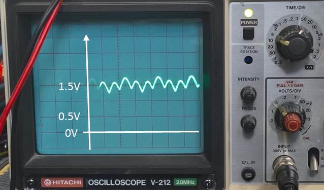
Initially this was done measuring open circuit and there was noticeable noise so it was then repeated using a 1kΩ resistor to mimic a load and this removed the noise (Figure xx below). It can be seen the diodes rectify the AC waveforms to DC successfully.

3-Phase (Full Bridge Rectifier) Testing
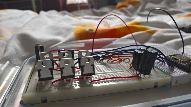
With the assistance and supervision of Douglas Carmichael, we were able to test the 3 phase input and DC output of the whole rectifier circuit. A 415V power supply had to be used, set initially at 0V and then gradually ramped up to 15V to supply all 3 inputs simultaneously, as shown in the photos below.


Having confirmed a DC output, from running it through the rectifier with diodes alone, we then repeated the procedure using the capacitor for smoothing to get a better idea of behaviour.
Overall output with capacitor is much smoother than predicted, with only one phase producing a slight pulse, but this is small enough to not cause any significant effect on the rest of the charging circuit components.

Conclusion
We found the rectifier output to be sufficiently smoothed by a 100μF capacitor and thus didn’t feel the additional cost of an inductor could be justified and so chose not to include one. The testing also measured an output of only around 2V from a 15V three phase AC input but this inefficiency is probably due to the test circuit being built on a breadboard with low power wires, and thus can be assumed to be significantly reduced in a final circuit on.
Next: The Control System
This is a sub-section of my posts describing the Sustainable Energy Design 3 course group project to Design and Build a Micro Wind Turbine – for more information see here
