

This is a sub-section of my posts describing the Sustainable Energy Design 3 course group project to Design and Build a Micro Wind Turbine – for more information see here
Overall System
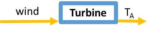
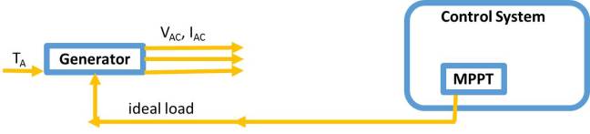
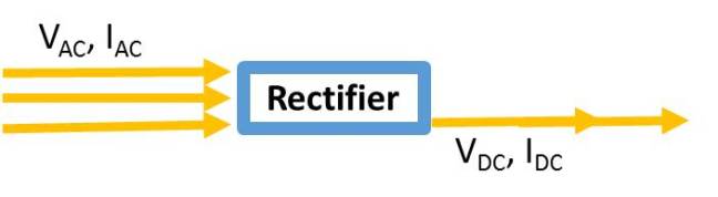
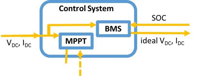
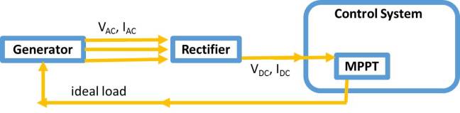
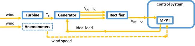
The control system is designed to monitor variables across the overall system and feedback so as to improve and optimise the outputs. The potential system for the turbine is shown in Figure 1 with the outputs and inputs labelled on the arrows.
There are two main different methods of monitoring and providing feedback and that is through either:
- hardware circuit design
- programming software design
Although mechanical methods are also possible, the relevant methods are generally too inefficient for this application.
Hardware used to be the most popular method of control in micro wind due to the smaller costs of components than the cost of a microcontroller necessary to run software, however as microcontrollers have become more popular over recent years, their cost has dropped and so this comparison is less relevant. As software allows for greater control of variables, allows them to be communicated in more useful formats (such a text file to be read on a computer as opposed to an LED screen display) and ease of correction, we are going to use software for our overall control system.
Turbine
Generator
Rectifier
Microcontroller
Battery Management System

Maximum Power Point Tracking
Wind Speed Measurement
Choice of Microcontroller
There are a variety of microcontrollers available, including those that are specialised with code already pre-written and implemented for use in similar systems to ours but as these are considerably more expensive than a generic, programmable one, we have decided to not use them.
Raspberry Pi
The Raspberry Pi is not just a microcontroller, but a microcontroller and other units containing many unnecessary features and components not relevant to this application. It was originally designed not so much to enable efficient connectivity for projects like this but to be used more as an educational tool.
Arduinos
The most popular generic microcontrollers are Arduinos which, due to their popularity, have a lot of resources and support available to them. However, they come with the problem of communication as further modules are necessary to implement effective connectivity. This means increasing workload an/or costs.
The basic modules were being offered pre-paid for by the University and we suspect some of Stein’s own personal supply so they would come with the advantage of that cost removed. However there were a limited supply available to the course, and I had my own personal supply of different microcontrollers that could be used and thus negating that advantage somewhat.
ARM mBeds
These at the time of the project were less accessible in terms of ease of development, amount of support available, and costs, in addition to the communication problem of the Arduinos.
Particle Cores
Particle Core microcontrollers were still relatively new at the time of the project, with more limited support than Arduinos or Raspberry Pis. However they use a variant of the C/C++ based Wiring as Arduino but just normally developed within the online Particle Core IDE, so its ease and time for development would be comparable to the Arduino, allowing me to tap into the larger Arduino support.
Additionally they had faster read times for quicker response for control system which makes it more effective at minimising losses.
Finally, and most importantly, you could get either the WiFi enabled ‘Photon’ or the 3G enabled ‘Electron’ both allowing users to maintain internet connectivity in a practical, wireless form.
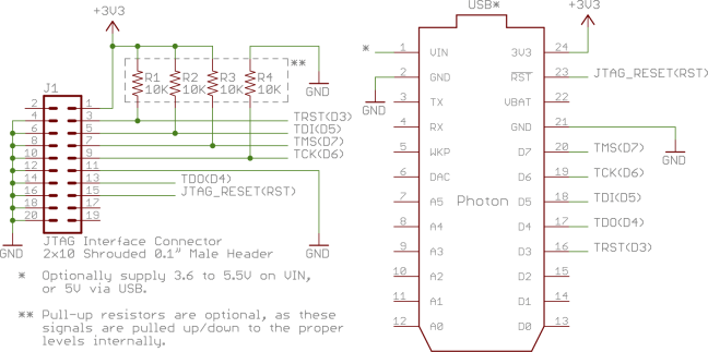
Particle Core Microcontroller
Therefore one of the two Particle Cores was chosen to be used. In the end, there was insufficient time left in the project to complete and test the control system and so the connectivity benefits were never trialled. I had not long received my Electron in the post from backing the Kickstarter campaign and so although the Photon may have been sufficient for demo purposes I developed on the Electron anyway and was rather gutted at never finishing.
The most important features of the microcontroller for our application:
- 8 channels (A0 to A7)
- 12-bit resolution
- it will map input voltages between 0 and 3.3 volts into integer values between 0 and 4095
- a resolution between readings of: 3.3 volts / 4096 units or, 0.0008 volts (0.8 mV) per unit.
- one AC-DC converter – every analogRead() has to be run serially through that one converter because that makes the fast read/write time periodic for each function, so the more readings I take, the less frequently each reading is taken.
Next: Battery Management System
This is a sub-section of my posts describing the Sustainable Energy Design 3 course group project to Design and Build a Micro Wind Turbine – for more information see here
