
This is a sub-section of my posts describing the Sustainable Energy Design 3 course group project to Design and Build a Micro Wind Turbine – for more information see here
Building the Rotor
So the theoretical design had pretty much outlined the magnet specification that we needed and so we had simply ordered that. The University was in complete chaos over ordering everything of course so it took a little while longer for them to actually arrive and there was a while when we weren’t even sure if that was actually going to happen but they did eventually.
Then we needed to house them. Theoretically this could be done in something as simple as MDF but of course the magnets being so expensive we had basically long ago run out of our very limited budget. As someone who enjoys upcycling and things like that, I was very aware of our local networks of free and secondhand things and so quickly suggested we try and get some appropriate wood or board through something like that.
I scoured Gumtree, Freegle, Freecycle, local Facebook groups, and local scrap and swap shops.


Eventually I accumulated various pieces:
- A huge piece of marine plywood from a very lovely woman in Inverleith who was very enthusiastic about our project, via a Facebook group. In order to actually achieve cost savings I did not get the bus but walked from Inverleith to Tollcross in the wind with a huge piece of flexible plywood. This was a mistake. I could not feel my fingertips by the time I got back
- Various small pieces of timber and board, and several large metal poles from a free swap and scrap shop in St Margaret’s House in Meadowbank. Not having learned my lesson from the marine plywood, I decided to walk these home alone too. They weren’t difficult to walk but the route took me via Holyrood Palace and the Scottish Parliament in the dark which would be fine, I thought. Then as I approached someone walking along the path towards me basically jumped and then ran past me at super speed, making me turn around in fright to see nothing. I realised that in the dark it might have looked like I was marching weapons towards Queen and country. I was then so nervous someone would arrest me for being so suspicious looking that I nearly ran the rest of the way back.
- PVC piping… From a dismantled toilet. Stolen from the skip, in the dark, of the building next door who were clearly renovating their toilet room. My flatmate was a mixture of bemused and horrified when I told her that I had seen some good piping in the skip, and then crept out to steal it. The horror mainly came from keeping the piping uncleaned on our kitchen floor until I could get it into the labs the following day. The team were also unnerved by my discovery and eventually tentatively cleaned it with plans to use it for the turbine features but ultimately never used it anyway.
Let no one ever doubt my commitment to trying to keep an engineering project on budget ever again.
Anyway, this gave us enough board to both make the rotor and waterproof housing for the generator as well which was fantastic.


Building the Stator
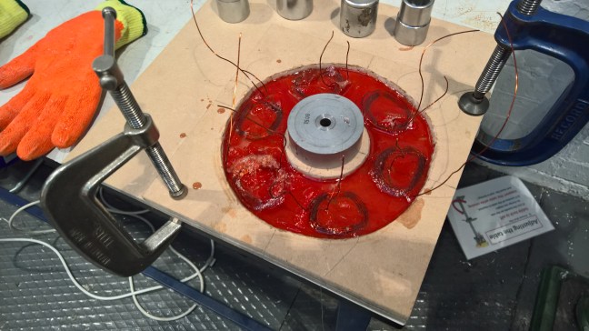
We began by creating a mould to use to bend the 6 coils into shape. This was done using a plastic disc through which 4 pins were inserted, outlining the inner shape of the trapezoid around which to bend the wire, as shown in the pictures below. This was a surprisingly fiddly process because the wire was very springy, and really did not want to hold its new trapezoidal shape at all, but bending it too far to try and hold it in then made it want to overlap with the adjacent parallel wires which would be terrible for the generator properties.
Realising pretty quickly that we’d need to hold the coils in shape somehow before we could set them in the stator mould, but also concerned about increasing the gap between the stator coils and rotor magnets by adding layers such as through wrapping them in tape, we decided to try and use glue.With hindsight I wish we could have had the time to experiment with different methods for their effectiveness at holding the shapes and especially once set into the mould resin. And additionally a lot more practice at formaing the coil shapes would have been really helpful. Alas, we were pressed for time with all the delays and so proceeded with the hot glue gun that we were able to borrow and used the first reasonable looking coils we were able to make.
A second plastic disc with a cut out section was clamped on top of the pins to try and ensure the wires stayed aligned during winding, and limit their ability to jump up and overlap with each other. Being very thin wires, it was difficult to hold the two pieces together tightly enough to be effective at that, and still be able to wind through the middle. Additionally, not being able to see the windings underneath the top half wasn’t helpful.
We cut out a section to allow some access to the coil to use the hot glue to hold the wires in place after winding. Excess wire was left at each end of the coil to be soldered to extension wires connected to the charging circuit.


We waxed the board to be used as the mould and then put down one initial layer of carbon fibreglass and resin for the windings to just sit in as we hoped that this would be enough to them hold them in place, as well as shape, when we then filled the rest of the resin in on top. Because they were still springing up and unravelling out of the glue blobs once out of the clamps, we found things to act as weights and press them down into this first layer of resin whilst it set.


It was vaguely successful, in that most of the coils stayed more or less tightly wound but not overlapping. However, a couple of them started unraveling as the resin got in around the glue gun glue when the rest of the mould was being filled in and we tried to push one of them back down – but the fibreglass was nearly set and so was too brittle and started cracking instead of flowing down. This not only worsened the shape of that one coil, but also made us too scared to attempt anything in the remaining time for the second.
On one hand, the side with the thick but cracked fibreglass is not the layer facing the rotor, that remained flat along the mould base. However, the coil’s shapes were not great, and knowing the sensitivity of the whole system to millimetres of precision needed, it wasn’t great.
We held the centrepiece of the mould down with a weight once it had been precisely aligned and then layered the remaining carbon fibre sheets and poured the remaining resin in.
Once the resin had set we then needed to remove the mould from the stator itself. Initially we sawed off the excess board around the perimeter and peeled some of the remaining strips of board away cleanly from the wax layer.
But we had more problems – the resin appeared to have seeped between the two layers of MDF of the mould where it hadn’t been waxed and so stuck to the board. As the resin was one whole piece that meant that the stator was stuck to the mould by its edges. Being very brittle, we didn’t feel it advisable to try and and cut through the centre or any closer to the outside edges in case we created a crack in the excess resin that would propagate through to the main stator piece itself.
We were exploring the various tools and resources we could see in the Mechanical Teach Lab to try and find a solution when Natasha, looked at us all very calmly and told us to just dissolve it. Never were we all so grateful for having a chemical engineer on the team as in that moment.

So we used one of the many tupperware boxes borrowed from my flat (they are too useful) to rest it in water, knowing how terribly MDF deals with the stuff and hoping that it would distort it enough to let us peel it away.
After a day it wasn’t looking promising so I kidnapped our little stator back to my flat where I filled the tupperware with lots of lovely nail varnish remover as I was very familiar with those chemicals for removing things from my experience with lots of acetone and isopropanols in the Vacuum Science group on my Year In Industry.
My ever wonderful flatmate Mairi wasn’t best pleased at me filling the living room with evaporating acetones, that being the room in our flat that I was able to open the windows the widest (but still not very wide, yay Scottish tenement flats) so at least we wouldn’t die of the fumes.
However, it was worth it as Natasha’s genius idea worked and we got the MDF clean off as you can see from the photo below.

Final Assembly
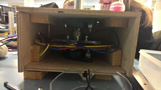
The rest of the team had done a fantastic job of designing and building the housing for the generator with a special shout out to Omar for his fantastic CAD modelling skills.
Not so great was our discovery that the slightly lower grade of bearings that we had had to order because of the budgetary and supplier constraints were terrible. We never measured how much torque would actually be needed to move those bearings because I don’t think any of us wanted to acknowledge how much of our engineering work was simply being wasted in that one set of components.
Again, if only we’d had the freedom to do some more testing but it was not to be.
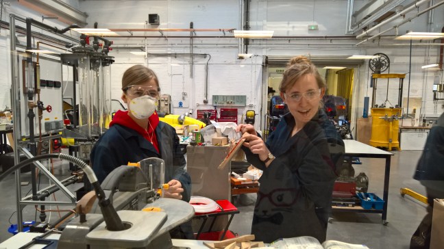
Nonetheless, we moved on and Ellen and I chilled out in the micro electronics lab who were utterly terrified of our powerful magnets, while we soldered cabling to the generator coils. We then assembled the whole thing together to make the beautiful masterpiece in the picture below.
Testing
So we actually ended up having two rather unsatisfying rounds of testing. The first, showed no power being produced at all. Armed with a good old multimeter and some assistance from the ever patient Martin Reekie, we managed to identify the cause as terrible connections between the coil wiring and the cabling.
We disassembled the generator.
And learned that you need to scrape away a lot of the coating from the wiring before you can make a strong solder connection. Well at least I know now.
Then we reassembled the generator.
And it still didn’t work. But sadly we never got the time beyond that to look much more closely at it as the Easter holidays, all my other coursework deadlines, and exams happened. At some point I will once again kidnap the generator out of the mechanical lab (if it is hopefully still in there somewhere) and look at it again more closely. Maybe even have an attempt at redoing that flipping stator again properly, if I think I can get all the things relatively cheaply somewhere. Maybe. Maybe I’ll just lament forever the fact that I never got my generator to work on time. It’s a devastating life being an engineer, especially when you anthropomorphise half your projects and become too emotionally attached to them.
Next: The Rectifier Circuit
This is a sub-section of my posts describing the Sustainable Energy Design 3 course group project to Design and Build a Micro Wind Turbine – for more information see here
